Powerline Frequency Switching and EMI Generation
In modern electrical systems, devices that switch at powerline frequencies can inadvertently become sources of electromagnetic interference (EMI). Whether through mechanical contacts or solid-state components, the process of controlling power often introduces electrical noise that can disrupt other electronic equipment.
Mechanisms of Interference
Interference typically originates from two primary sources: mechanical sparking and solid-state switching. Hardware operating on power lines can generate sparks at rates of either 100 Hz or 120 Hz, depending on the regional mains frequency. While a spark at a physical contact acts as a wide-band source—meaning its frequency is not directly tied to the power supply frequency—solid-state devices behave differently.
Solid-state power control devices, such as light dimmers, are frequent contributors to EMI. Specifically, regulators utilizing Thyristors (Silicon Controlled Rectifiers or SCRs) and TRIACs (Triode for Alternating Current) can generate significant interference if they are not paired with proper chokes to filter the output.
Phase Angle Control and Harmonics
Many thyristor-based power controllers employ the variable phase angle method. This technique controls the amount of power delivered to a load by delaying the point at which the device begins to conduct during each half-cycle of the AC waveform. Because this creates a sharp switching action, it generates harmonics—multiples of the fundamental mains supply frequency—which can propagate as noise through the electrical system.
Mitigating EMI with Zero Crossing Switching
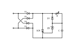
To minimize the potential for EMI problems in thyristor control systems, engineers often implement zero crossing switching. This method ensures that the thyristor is switched on precisely at the moment the AC voltage transitions from one direction to the other (the zero-voltage point), thereby reducing the abrupt current spikes that cause interference.
Key Facts
- Power line hardware can produce sparks at frequencies of 100 Hz or 120 Hz.
- Mechanical contact sparks are wide-band noise sources unrelated to supply frequency.
- Thyristor (SCR) and TRIAC regulators without chokes are common EMI sources.
- Variable phase angle control generates harmonics of the mains supply.
- Zero crossing switching is an effective technique for reducing EMI in thyristor systems.
| Source Type | Mechanism | Frequency Characteristic | Mitigation Strategy |
|---|---|---|---|
| Mechanical Contacts | Sparking | Wide-band (not supply-related) | Physical shielding/filtering |
| Solid-State (SCR/TRIAC) | Phase Angle Control | Mains supply harmonics | Chokes or Zero Crossing Switching |
Frequently Asked Questions
What is the difference between spark interference and thyristor interference?
Sparking at a contact creates a wide-band source of interference that is not related to the power supply frequency, whereas thyristor controllers using phase angle control generate harmonics specifically related to the mains supply frequency.
What are SCRs and TRIACs?
SCR stands for Silicon Controlled Rectifier (a type of thyristor), and a TRIAC is a Triode for Alternating Current. Both are solid-state components used to regulate power in devices like light dimmers.
How does zero crossing switching reduce EMI?
Zero crossing switching reduces EMI by triggering the thyristor only when the AC voltage is at or near zero volts, avoiding the sharp current transitions that create electrical noise.
Why are chokes used with TRIAC regulators?
Chokes are used to filter the output of TRIAC and thyristor regulators to prevent the electromagnetic interference generated during switching from affecting other devices on the power line.
At what rates do power line sparks typically occur?
Power line hardware typically generates sparks at a rate of either 100 Hz or 120 Hz.