CIGS Solar Cells: High-Efficiency Thin-Film Photovoltaic Technology
Copper Indium Gallium Selenide (CIGS) solar cells represent a sophisticated leap in thin-film photovoltaic (PV) technology. Unlike traditional solar panels that rely on thick silicon wafers, CIGS cells are created by depositing a thin layer of a solid solution—composed of copper, indium, gallium, and selenide—onto a backing of glass or plastic. This architecture allows for a lightweight, versatile energy solution that can be integrated into a variety of surfaces.
The primary advantage of CIGS lies in its high absorption coefficient, meaning the material is exceptionally efficient at capturing sunlight. Because it absorbs photons so strongly, the active semiconductor layer can be significantly thinner than those used in other technologies without sacrificing performance.
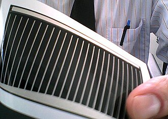
Key Facts
- Composition: A thin-film semiconductor made from copper, indium, gallium, and selenium.
- Efficiency: Laboratory research cells have reached a record efficiency of 23.64% as of 2024.
- Versatility: Can be deposited on rigid glass or flexible polymer substrates.
- Market Position: One of three mainstream thin-film technologies alongside cadmium telluride and amorphous silicon.
- Key Advantage: Higher absorption coefficient allows for much thinner layers than crystalline silicon.
Technical Structure and Properties
CIGS cells are typically manufactured as polycrystalline thin films. The device structure involves the CIGS absorber layer sandwiched between electrodes that collect the generated electric current. While some designs include a cadmium sulfide (CdS) buffer layer, newer iterations aim to be cadmium-free to reduce environmental impact.
![Figure 1: Structure of a CIGS device. CdS is used optionally and some CIGS cells contain no cadmium at all.[7]](/images/0b/88/0b8833bc4b342c8ba8143c2c2942fe27b98a794c1d17ff9f69873f755f71b121.jpg)
The Role of Bandgap Engineering
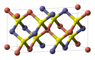
The bandgap—the energy required to excite an electron to a conductive state—is critical for efficiency. By alloying copper indium selenide (CIS) with copper gallium selenide (CGS), engineers can increase the bandgap. While a ratio of roughly 0.7 Ga/(In+Ga) is theoretically optimal for a 1.5 eV bandgap, industry standards typically target a 0.3 ratio, resulting in bandgaps between 1.1 and 1.2 eV to maintain better device performance.
Conversion Efficiency and Performance
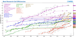
CIGS technology has consistently pushed the boundaries of thin-film efficiency. While crystalline silicon remains the market leader, CIGS outperforms polysilicon at the individual cell level, though its overall module efficiency is lower due to the complexities of upscaling production.
Research institutions including the National Renewable Energy Laboratory (NREL), Empa (Switzerland), and ZSW (Germany) have all reported cell efficiencies around 20%. In 2024, a new record of 23.64% was claimed. Flexibility also plays a role; while glass substrates generally yield the best performance, CIGS cells on flexible polymer foils have achieved efficiencies as high as 20.4%.
Efficiency by Substrate
The material used for the backing significantly impacts the final efficiency of the cell. The following table summarizes the performance across different substrates:
| Substrate | Efficiency | Leading Institute/Source |
|---|---|---|
| Glass | 23.6% | Uppsala University/Evolar |
| Polymer | 20.4% | Empa |
| Steel | 17.7% | Empa |
| Aluminium | 16.2% | Empa |
Manufacturing and Production Methods
Producing CIGS films requires precise deposition techniques. One of the most critical steps is selenization, where selenium is incorporated into the absorber. Using hydrogen selenide (H2Se) allows for faster incorporation and better uniformity at lower temperatures (400 °C), though it is highly toxic. Elemental selenium requires temperatures above 500 °C for full incorporation.
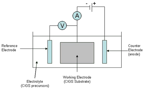
Various production methods are employed by industry leaders and researchers:
- Sputtering: Metallic layers are sputtered and then selenized. Some companies, like Showa Shell, use sulfurization to create a cadmium-free buffer layer.
- Coevaporation: A common method for high-efficiency lab cells.
- Electrodeposition: A process used to create the precursor layers before selenization.
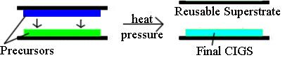
- Wafer-bonding inspired techniques: Innovative methods to combine precursor layers.
Market Landscape and Comparison
The thin-film market has historically struggled against the dominance of crystalline silicon, with thin-films holding roughly 15% of the market. CIGS specifically held about 2% of the market in 2013. While several early pioneers like Solyndra and Nanosolar faced bankruptcy, the Japanese company Solar Frontier remains a market leader. Other producers, such as Global Solar and GSHK Solar, focus on modules free of heavy metals like lead and cadmium.
Compared to other thin films, CIGS has often held the lead in efficiency. While cadmium telluride (CdTe) and amorphous silicon (a-Si) are also mainstream, CIGS has historically offered a more favorable tradeoff between material usage and light-gathering efficiency.
Frequently Asked Questions
What makes CIGS different from traditional silicon solar cells?
CIGS is a thin-film technology, meaning it uses a very thin layer of semiconductor material deposited on a substrate, whereas traditional cells use thick bulk silicon wafers. This makes CIGS lighter and potentially flexible.
Can CIGS solar cells be flexible?
Yes. Because the CIGS layer is so thin, it can be deposited on flexible polymer foils or plastics, allowing the resulting solar panels to bend.
What is the current record efficiency for CIGS?
As of 2024, a CIGS solar cell efficiency record of 23.64% has been claimed.
Are CIGS solar cells environmentally friendly?
While some CIGS cells use cadmium sulfide (CdS) as a buffer layer, many modern manufacturers are developing cadmium-free and lead-free modules to reduce environmental impact.
Why is the Ga/(In+Ga) ratio important?
This ratio determines the bandgap of the cell. Adjusting the amount of gallium relative to indium allows engineers to tune the cell to better absorb specific parts of the solar spectrum, though ratios above 0.3 typically lead to a drop in performance.